Arduino Infrared controller
| item | Quantity |
|---|---|
| SparkFun RedBoard | 1 |
| IR receiver | 1 |
| 330 Ω\OmegaΩ resistor | 1 |
| Jumper | 3 |
| Cable | 1 |
| item | Value |
|---|---|
| Arduino UNO Board | 1 |
| Infrared LED | 1 |
| 330 Ω\OmegaΩ resistor | 1 |
| 1 KΩ\OmegaΩ resistor | 1 |
| Bottom | 1 |
| Jumper | 7 |
| Cable | 1 |
— Graphs are created by using Autodesk Tinkercad
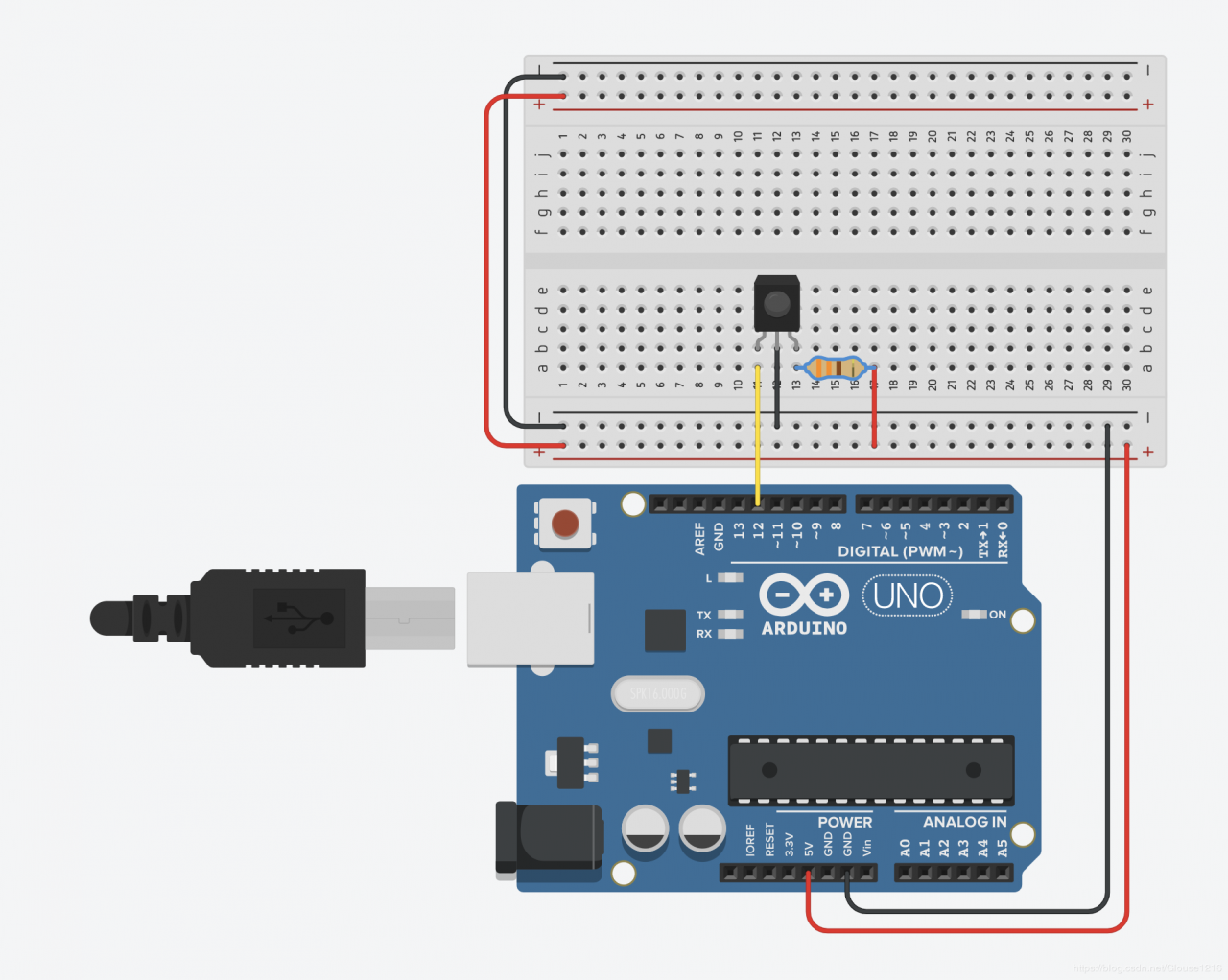
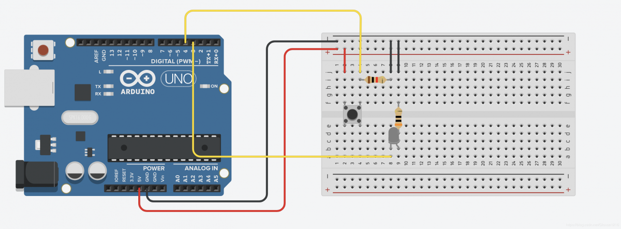
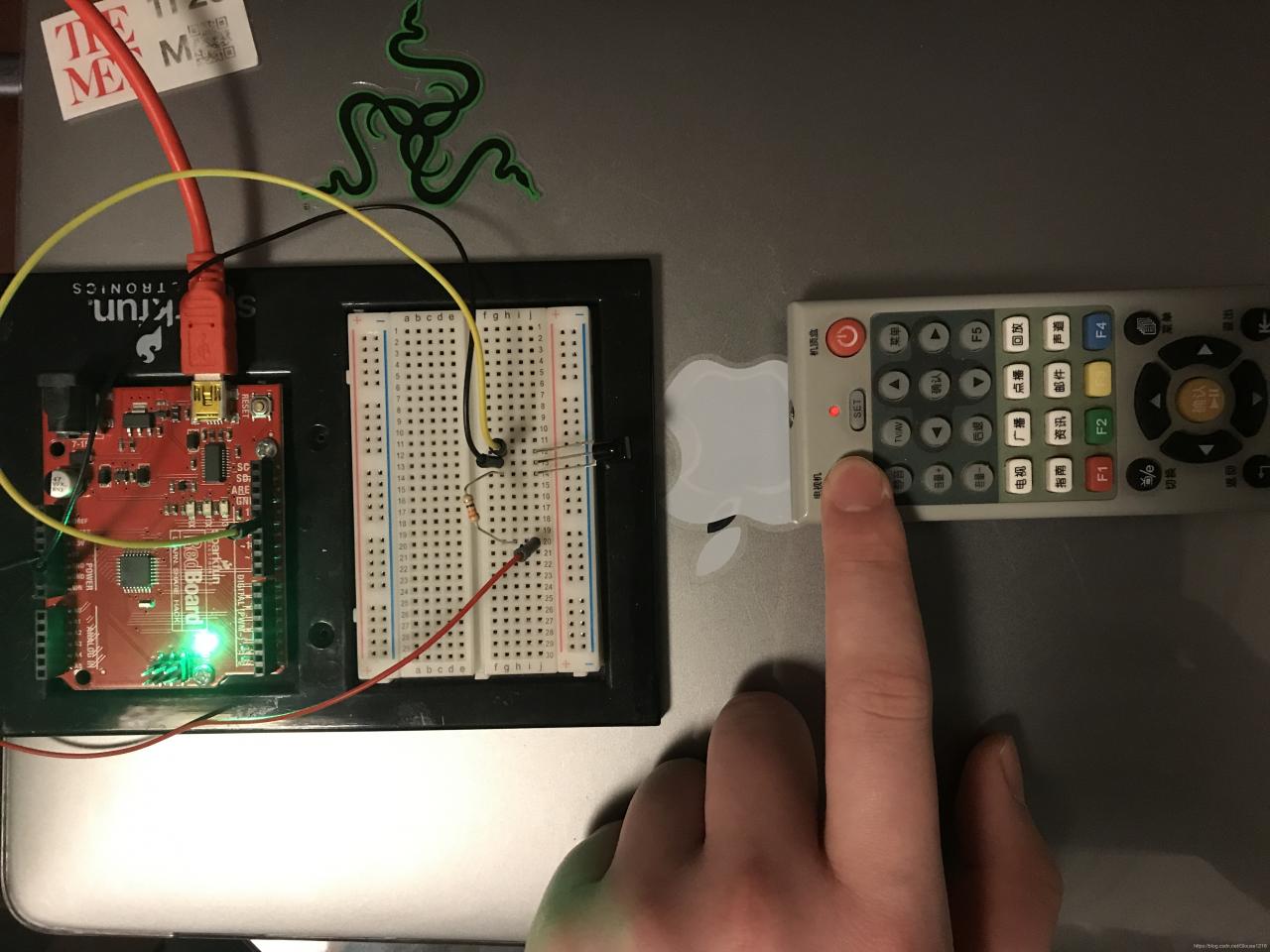
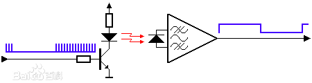
Picture:
The red one is receiver. Blue one is transmitter.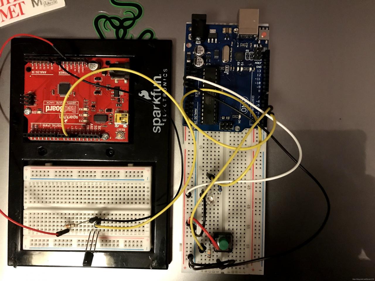
 2. Receiver code
#include "IRremote.h"
int RECV_PIN = 12; //Define Receiver PinNumber 12
int a = 0;
IRrecv irrecv(RECV_PIN); //Create the receiver object
decode_results results; //Define results
void setup()
{
    Serial.begin(9600);
    irrecv.enableIRIn();     // Initializes the infrared receiver
}
void loop() {
    if (irrecv.decode(&results)) {// return true
        Serial.println(results.value, HEX); // HEX hexadecimal, or base 16
        irrecv.resume(); // After receiving, this must be called to reset the receiver
                         // and prepare it to receive another code.
    }
    delay(110);
}
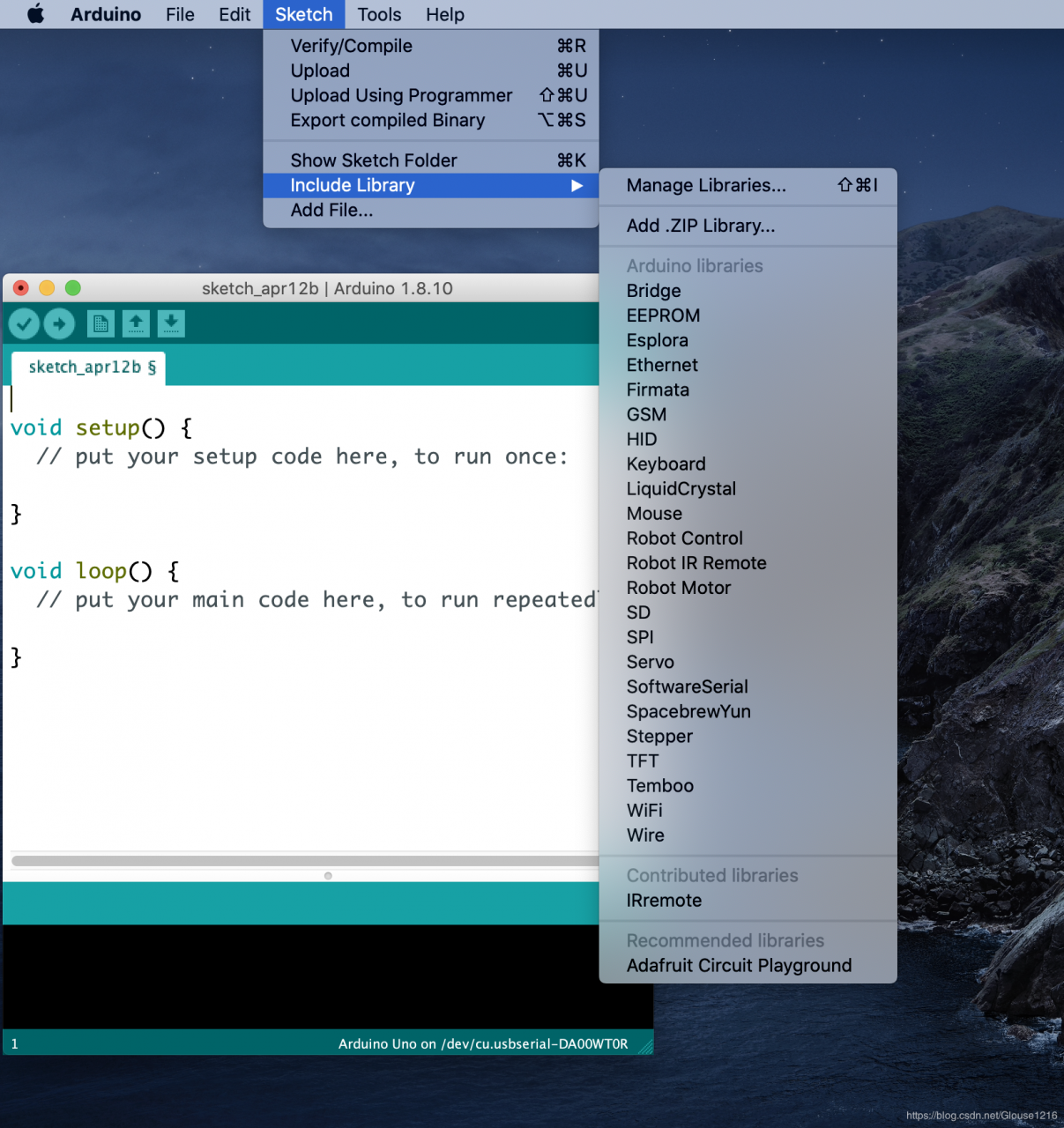
3. Transmitter code
#include
const int buttonPin = 4; // Define Button PinNumber 4
int buttonState = 0; //Initial states =0
IRsend irsend; //Define infrared
void setup()
{
pinMode(buttonPin, INPUT); // Setting Button Pin4 = Input
}
void loop()
{
buttonState = digitalRead(buttonPin);// Read 0 or 1
if (buttonState == HIGH) { //if 1 Sending messages
irsend.sendNEC(0x4CB3817E, 32);   // Sending NEC code
}
3. Build a TV controller
Step 1
Upload code into board, open the Serial Monitor.
Recording signal from TV controller.
We can see NEC code of the signal for turn on/ turn off is 4AB0F7B6.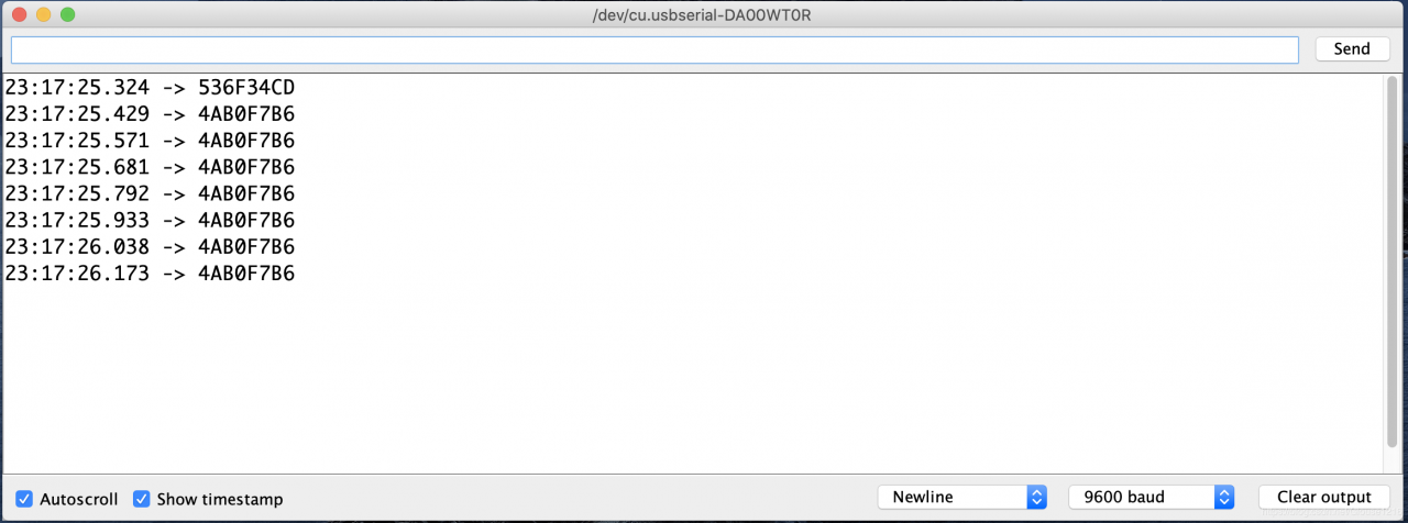
Open the transmitter code and update signal to 4AB0F7B6. Upload transmitter code to Arduino(transmitter)
Step 4Testing!!!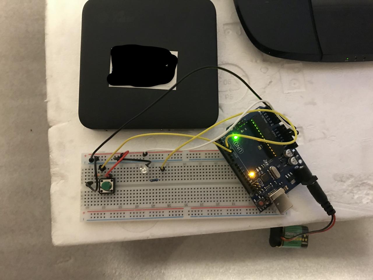
The NEC Infrared Transmission Protocol uses pulse distance encoding of the message bits. Each pulse burst (mark – RC transmitter ON) is 562.5µs in length, at a carrier frequency of 38kHz (26.3µs).
Logical bits are transmitted as following:
Logical ‘0’ – a 562.5µs pulse burst followed by a 562.5µs space, with a total transmit time of 1.125ms
Logical ‘1’ – a 562.5µs pulse burst followed by a 1.6875ms space, with a total transmit time of 2.25ms
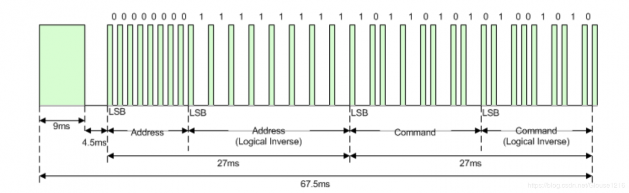
The NEC system is 32 bits in Binary number systems which can be translated to 8 bits in Hex number system. It is more convenient to read for human.
In C/C++, Hex number must started with 0x
3. Why carrier frequency is 38Hz?The range of carrier frequency always in 38Hz to 60Hz.
The range is decided by the crystal oscillator at topic. The frequency of crystal oscillator in IR LED is 455Hz. After a frequency divide processing, (455Hz /12 ≈\approx≈ 38Hz) We get a frequency which is 38Hz.
Frequency of Single-Chip Microcomputer . Crystal oscillator is 8
PDM
PDM is a method of reducing the average power delivered by an electrical signal, by effectively chopping it up into discrete parts.
Duty cycle
A duty cycle or power cycle is the fraction of one period in which a signal or system is active.
A nice duty cycle will help with balance between IR led overheating and controlling distance.
The NEC protocol choose 33% as duty cycle rate. (562.5/ 1.6875 = 0.333333…)
作者:Glouse1216