OpenCV通过透视变换实现矫正图像详解
目录
1、概述
2、代码演示
3、示例图片
1、概述案例:使用OpenCV将一张折射的图片给矫正过来
实现步骤:
1.载入图像
2.图像灰度化
3.二值分割
4.形态学操作去除噪点
5.轮廓发现
6.使用霍夫直线检测,检测上下左右四条直线(有可能是多条,但是无所谓)
7.绘制出直线
8.寻找与定位上下左右是条直线
9.拟合四条直线方程
10.计算四条直线的交点,ps:这四个交点其实就是我们最终要寻找的,用于透视变换使用的
11.进行透视变换
12.输出透视变换的结果
说明:
解释一下为啥是上面那些步骤。
1.其实我们的最终目的是通过透视矩阵getPerspectiveTransform+透视变换warpPerspective来完成图像的矫正
2.但是getPerspectiveTransform需要两个参数,输入矩阵参数和目标矩阵参数。
3.由于输入矩阵参数就是原图像是个角的顶点,由于我们没有所以要求出来
4.所以我们以上的所有步骤都是为11、12步打基础的
ps:核心就是利用透视矩阵做透视变换
重点:
1.直线方程y=kx+c
2.如果两条直线有交点,则必有k1x1+c1=k2x2+c2
2、代码演示//【1】载入图像
Mat src = imread(filePath);
if(src.empty()){
qDebug()<<"图片为空";
return;
}
imshow("src",src);
//【2】图像灰度化
Mat gray;
cvtColor(src,gray,COLOR_BGR2GRAY);
//【3】执行二值分割
threshold(gray,gray,0,255,THRESH_BINARY_INV|THRESH_OTSU);
imshow("threshold",gray);
//【4】执行形态学开操作去除图像中的造点
Mat kernel = getStructuringElement(MORPH_RECT,Size(5,5),Point(-1,-1));
morphologyEx(gray,gray,MORPH_CLOSE,kernel,Point(-1,-1),3);
imshow("morphologyEx",gray);
//【5】轮廓发现
bitwise_not(gray,gray);
imshow("bitwise_not",gray);
vector<vector<Point>> contours;
vector<Vec4i> hier;
RNG rng(12345);
findContours(gray,contours,hier,RETR_TREE,CHAIN_APPROX_SIMPLE);
Mat colorImage = Mat::zeros(gray.size(),CV_8UC3);
for(size_t i = 0;i<contours.size();i++){
Rect rect = boundingRect(contours[i]);
//过滤目标轮廓
if(rect.width<src.cols-5&&rect.height<src.rows-5&&rect.width>src.cols/2){
drawContours(colorImage,contours,i,Scalar(rng.uniform(0,255),rng.uniform(0,255),rng.uniform(0,255)),1);
}
}
imshow("findContours",colorImage);
//【6】使用霍夫直线检测
vector<Vec4i> lines;
cvtColor(colorImage,colorImage,COLOR_BGR2GRAY);
kernel = getStructuringElement(MORPH_RECT,Size(3,3),Point(-1,-1));
dilate(colorImage,colorImage,kernel,Point(-1,-1),1);
imshow("colorImage_gray",colorImage);
int accu = min(src.cols*0.5, src.rows*0.5);
HoughLinesP(colorImage,lines,1,CV_PI/180,accu,accu,0);
//【7】绘制出直线
Mat lineColorImage = Mat::zeros(gray.size(),CV_8UC3);
qDebug()<<"line count:"<<lines.size();
for(size_t i = 0;i<lines.size();i++){
Vec4i ll = lines[i];
line(lineColorImage,Point(ll[0],ll[1]),Point(ll[2],ll[3]),Scalar(rng.uniform(0,255),rng.uniform(0,255),rng.uniform(0,255)),2,LINE_8);
}
imshow("lines",lineColorImage);
//【8】寻找与定位上下左右四条直线
int deltah = 0;
int width = src.cols;
int height = src.rows;
Vec4i topLine, bottomLine;
Vec4i leftLine, rightLine;
for(size_t i=0;i<lines.size();i++){
Vec4i ln = lines[i];
deltah = abs(ln[3]-ln[1]);//直线高度
if (ln[3] < height / 2.0 && ln[1] < height / 2.0 && deltah < accu - 1) {
if (topLine[3] > ln[3] && topLine[3]>0) {
topLine = lines[i];
} else {
topLine = lines[i];
}
}
if (ln[3] > height / 2.0 && ln[1] > height / 2.0 && deltah < accu - 1) {
bottomLine = lines[i];
}
if (ln[0] < width / 2.0 && ln[2] < width/2.0) {
leftLine = lines[i];
}
if (ln[0] > width / 2.0 && ln[2] > width / 2.0) {
rightLine = lines[i];
}
}
//直线方程y=kx+c
// 【9】拟合四条直线方程
float k1, c1;
k1 = float(topLine[3] - topLine[1]) / float(topLine[2] - topLine[0]);
c1 = topLine[1] - k1*topLine[0];
float k2, c2;
k2 = float(bottomLine[3] - bottomLine[1]) / float(bottomLine[2] - bottomLine[0]);
c2 = bottomLine[1] - k2*bottomLine[0];
float k3, c3;
k3 = float(leftLine[3] - leftLine[1]) / float(leftLine[2] - leftLine[0]);
c3 = leftLine[1] - k3*leftLine[0];
float k4, c4;
k4 = float(rightLine[3] - rightLine[1]) / float(rightLine[2] - rightLine[0]);
c4 = rightLine[1] - k4*rightLine[0];
// 【10】四条直线交点,其实最终的目的就是找这是条直线的交点
Point p1; // 左上角
p1.x = static_cast<int>((c1 - c3) / (k3 - k1));
p1.y = static_cast<int>(k1*p1.x + c1);
Point p2; // 右上角
p2.x = static_cast<int>((c1 - c4) / (k4 - k1));
p2.y = static_cast<int>(k1*p2.x + c1);
Point p3; // 左下角
p3.x = static_cast<int>((c2 - c3) / (k3 - k2));
p3.y = static_cast<int>(k2*p3.x + c2);
Point p4; // 右下角
p4.x = static_cast<int>((c2 - c4) / (k4 - k2));
p4.y = static_cast<int>(k2*p4.x + c2);
// 显示四个点坐标
circle(lineColorImage, p1, 2, Scalar(255, 0, 0), 2, 8, 0);
circle(lineColorImage, p2, 2, Scalar(255, 0, 0), 2, 8, 0);
circle(lineColorImage, p3, 2, Scalar(255, 0, 0), 2, 8, 0);
circle(lineColorImage, p4, 2, Scalar(255, 0, 0), 2, 8, 0);
line(lineColorImage, Point(topLine[0], topLine[1]), Point(topLine[2], topLine[3]), Scalar(0, 255, 0), 2, 8, 0);
imshow("four corners", lineColorImage);
// 【11】透视变换
vector<Point2f> src_corners(4);
src_corners[0] = p1;
src_corners[1] = p2;
src_corners[2] = p3;
src_corners[3] = p4;
vector<Point2f> dst_corners(4);
dst_corners[0] = Point(0, 0);
dst_corners[1] = Point(width, 0);
dst_corners[2] = Point(0, height);
dst_corners[3] = Point(width, height);
// 【12】获取透视变换矩阵,并最终显示变换后的结果
Mat resultImage;
Mat warpmatrix = getPerspectiveTransform(src_corners, dst_corners);
warpPerspective(src, resultImage, warpmatrix, resultImage.size(), INTER_LINEAR);
imshow("Final Result", resultImage);
3、示例图片
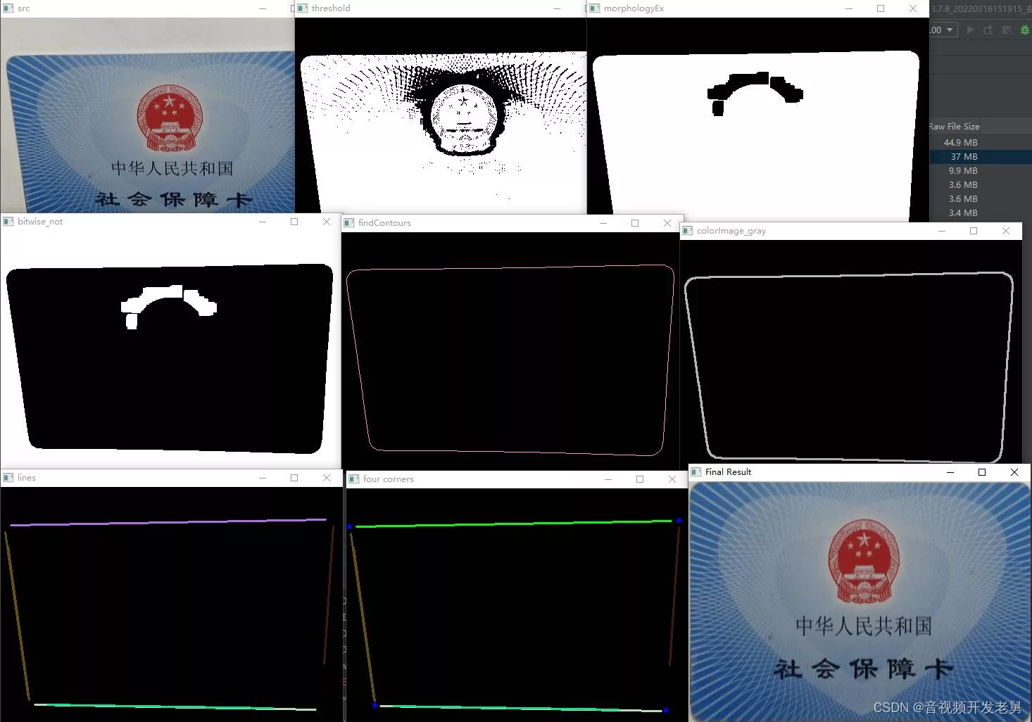
以上就是OpenCV通过透视变换实现矫正图像详解的详细内容,更多关于OpenCV矫正图像的资料请关注软件开发网其它相关文章!