使用RT-Thread 系统实现DIY数字仪表(四)——同步网络时间
1.使用RT-Thread 系统实现DIY数字仪表(一)——STM32CUBMX5.6移植touchGFX4.13
2.使用RT-Thread 系统实现DIY数字仪表(二)——把TouchGFX移植到RTThread系统
3.使用RT-Thread 系统实现DIY数字仪表(三)——获取温湿度传感器数据
4.使用RT-Thread 系统实现DIY数字仪表(四)——同步网络时间
5.使用RT-Thread 系统实现DIY数字仪表(五)——链接阿里云物联网平台
6.使用RT-Thread 系统实现DIY数字仪表(六)——完善TouchGFX仪表界面
7.使用RT-Thread 系统实现DIY数字仪表(七)——开发微信小程序
硬件: 野火挑战者STM32F767 V1开发版和ESP8266模块
软件: TouchGFXDesigner v4.13和 STM32CubeMX v5.6.0,MDK v5.29,RT-Thread env 工具
1.准备一套 野火挑战者STM32F767 开发版或其他核心板
2.安装 TouchGFXDesigner v4.13
3.安装STM32CubeMX v5.6.0和X_CUBE_TOUCHGFX软件包
4.安装 MDK v5.27以上版本
5.下载 RTThread源码包https://gitee.com/rtthread/rt-thread
代码持续更新中:github代码下载地址https://gitee.com/Aladdin-Wang/hellotouchGFX.git
联系作者:加微信备注touchgfx,拉入touchgfx-rtthread技术交流群共同学习

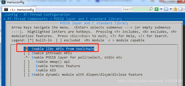
使用at_device软件包之前,需要先开启libc组件,touchgfx使用的C++编程语言,使用libc组件前,需要先打开C++组件支持
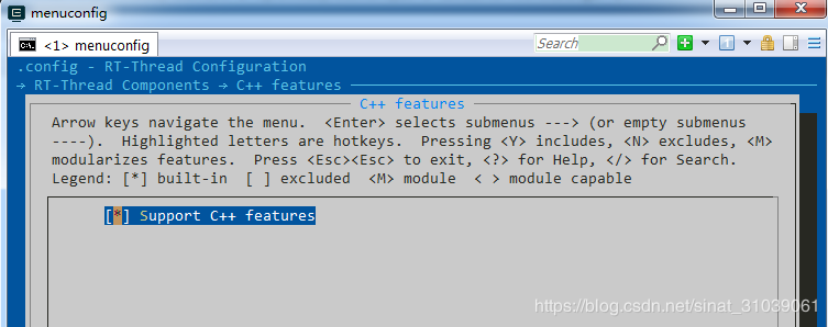
使用at_device软件包之前,需要先开启libc组件
AT device 软件包是对 AT 组件和 AT socket 功能的移植,需开启 AT 组件库和 AT socket 功能来获取 AT device 软件包。
RT-Thread online packages —>
IoT - internet of things —>
-*- AT DEVICE: RT-Thread AT component porting or samples for different device
[ ] Enable at device init by thread
AT socket device modules (Not selected, please select) —>
Version (V1.6.0) —>
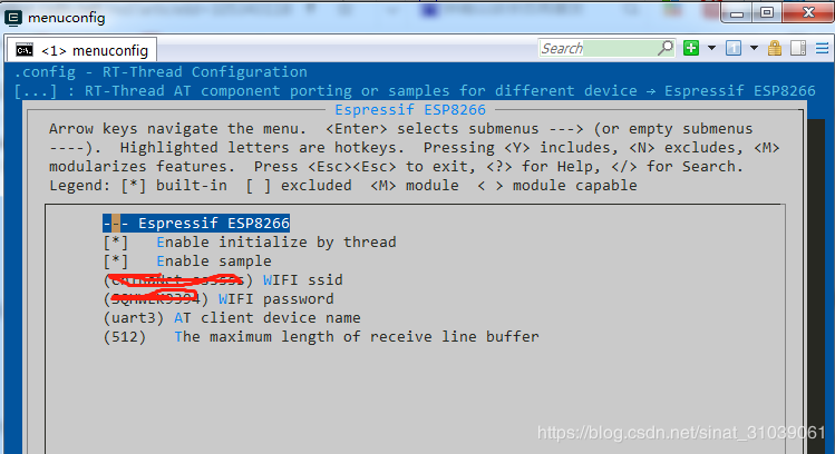
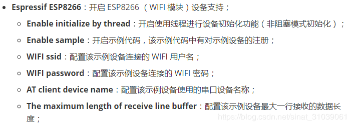
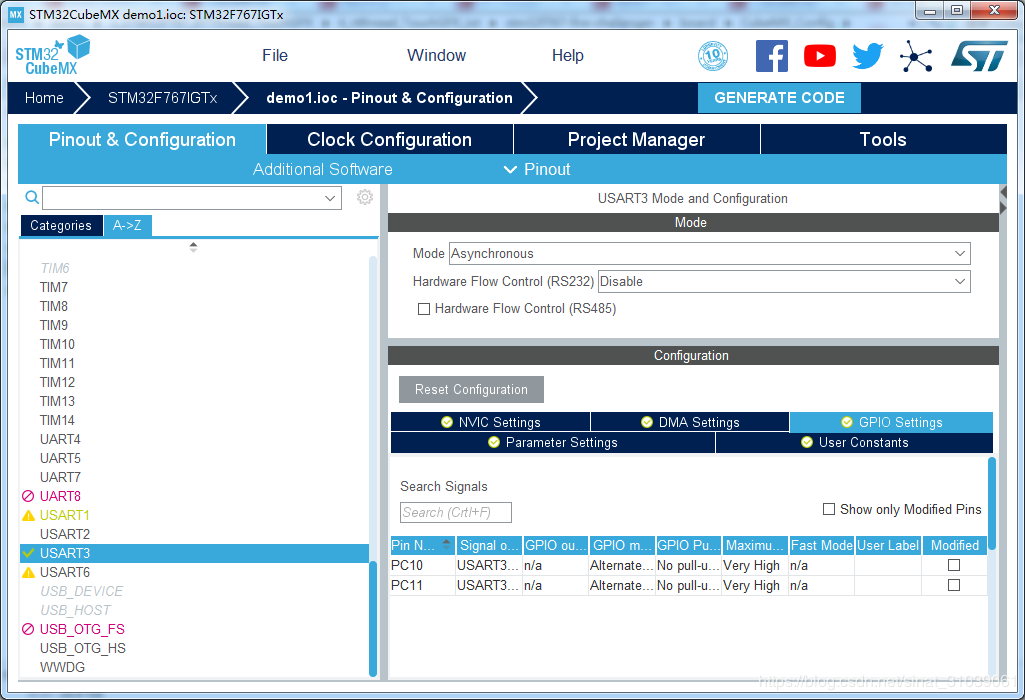
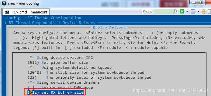
增加RX缓冲区大小:
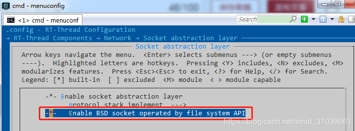
此时 net device和文件系统也将自动被打开(fd 的管理在文件系统中,所以需要文件系统):
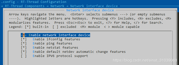
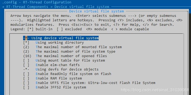
ifcong测试:

ping测试:

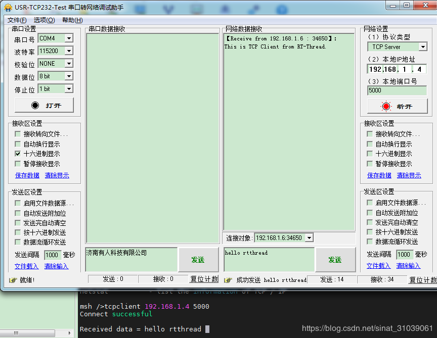
tcpclient测试:
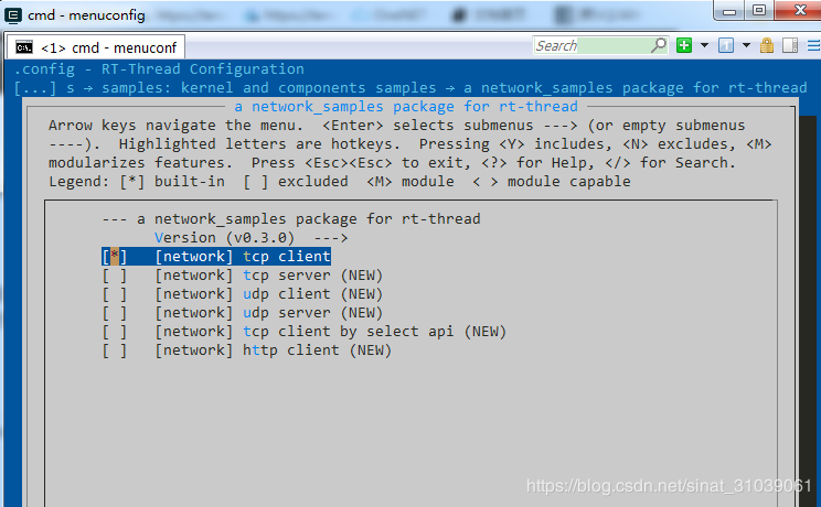
在软件包中开启基础示例代码 tcp client
-> RT-Thread online packages
-> miscellaneous packages
-> samples: kernel and components samples
-> a network_samples package for rt-thread
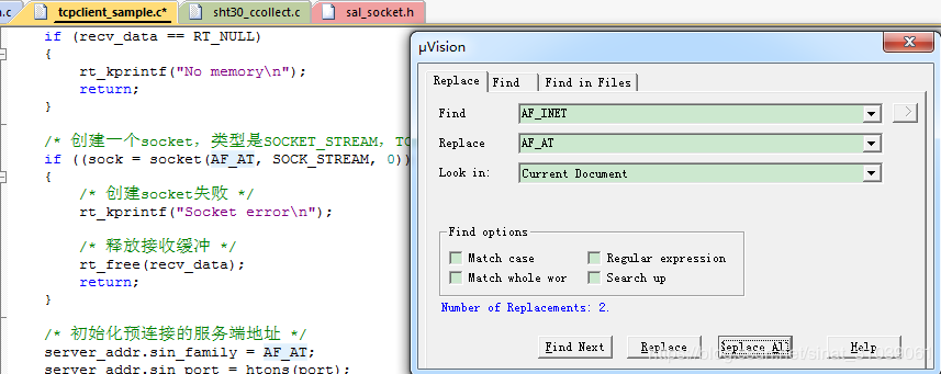
由于使用的是AT Socket 协议栈,所以把AF_INET替换成AF_AT
netutils软件包中汇集了 RT-Thread 可用的全部网络小工具集合,包括NTP工具。
NTP 是网络时间协议(Network Time Protocol),它是用来同步网络中各个计算机时间的协议,RT-Thread 上的 NTP 客户端连接上网络后,可以获取当前 UTC 时间,并更新至 RTC 中。
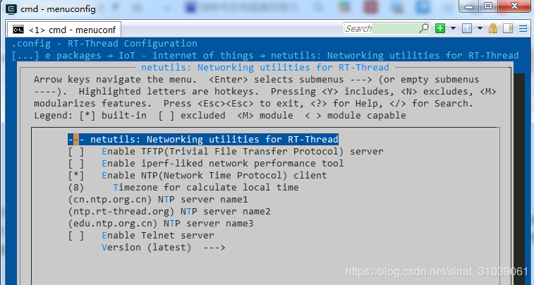
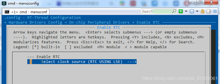
因为NTP工具在获取到网络时间后,需要同步到本地RTC,所以需要开启本地RTC功能
使用NTP工具包自带的命令进行测试:

#include
#include
#include
#include
#include
#include
/* defined the LED0 pin: PH10 */
#define LED0_PIN    GET_PIN(H, 10)
int main(void)
{
    int count = 1;
	time_t cur_time;
    /* set LED0 pin mode to output */
    rt_pin_mode(LED0_PIN, PIN_MODE_OUTPUT);
	rt_pin_write(LED0_PIN, PIN_HIGH);
	//获取网卡对象
	struct netdev* net = netdev_get_by_name("esp0");
	//阻塞判断当前网络是否正常连接
	while(netdev_is_internet_up(net) != 1)
	{
	   rt_thread_mdelay(200);
	}
	//提示当前网络已就绪
	rt_kprintf("network is ok!\n");
	cur_time = ntp_sync_to_rtc(NULL);
	if (cur_time)
	{
		rt_kprintf("Cur Time: %s", ctime((const time_t*) &cur_time));
	}
	else
	{
		rt_kprintf("NTP sync fail.\n");
	}
    while (count++)
    {
        rt_pin_write(LED0_PIN, PIN_HIGH);
        rt_thread_mdelay(1000);
        rt_pin_write(LED0_PIN, PIN_LOW);
        rt_thread_mdelay(1000);
    }
    return RT_EOK;
}
3.4 将网络时间同步到UI
使用SIMULATOR这个宏来区分vs仿真和使用hal库的代码
#ifndef SIMULATOR
#include "Thread.h"
#include
#endif
void mainView::handleTickEvent()
{
	#ifdef SIMULATOR
	/*使用VS仿真的代码*/
	tickCounter++;
    if (tickCounter % 60 == 0)
    {
        if (++digitalSeconds >= 60)
        {
            digitalSeconds = 0;
            if (++digitalMinutes >= 60)
            {
                digitalMinutes = 0;
                if (++digitalHours >= 24)
                {
                    digitalHours = 0;
                }
            }
        }
        if (++analogSeconds >= 60)
        {
            analogSeconds = 0;
            if (++analogMinutes >= 60)
            {
                analogMinutes = 0;
                if (++analogHours >= 24)
                {
                    analogHours = 0;
                }
            }
        }
        // Update the clocks
        digitalClock.setTime24Hour(digitalHours, digitalMinutes, digitalSeconds);
        analogClock.setTime24Hour(analogHours, analogMinutes, analogSeconds);
    }
	#else
	/*使用HAL库的代码*/
	time_t now;
	struct tm *clock;
	now = time(RT_NULL);
	clock = gmtime(&now);
	digitalHours = clock->tm_hour;
	digitalMinutes = clock->tm_min;
	digitalSeconds = clock->tm_sec;
	analogHours = clock->tm_hour;
	analogMinutes = clock->tm_min;
	analogSeconds = clock->tm_sec;
	digitalClock.setTime24Hour(digitalHours, digitalMinutes, digitalSeconds);
    analogClock.setTime24Hour(analogHours, analogMinutes, analogSeconds);
	#endif
}
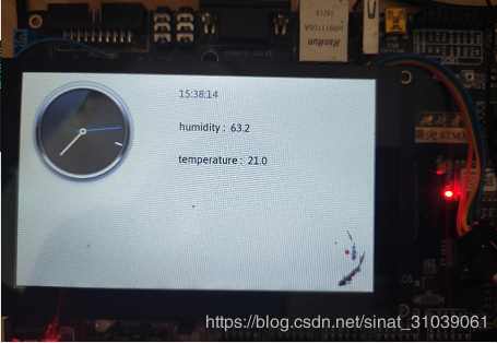
4 效果
上电获取时间:

UI同步时间:
扩展阅读:RT-Thread学习笔记之网络框架
作者:Aladdin Wang